Automazione Industriale

Meccatroinca

Meccatronica

Sicurezza Industriale

Componenti Quadri

Sensori e Sistemi di Visione

Pneumatica

Network e Comunicazione

Cavi Speciali

Accedi ai servizi

Entra nella tua area riservata

Accedi ai servizi

Entra nella tua area riservata

PHOENIX CONTACT 1104985
PHOENIX CONTACTNon disponibile

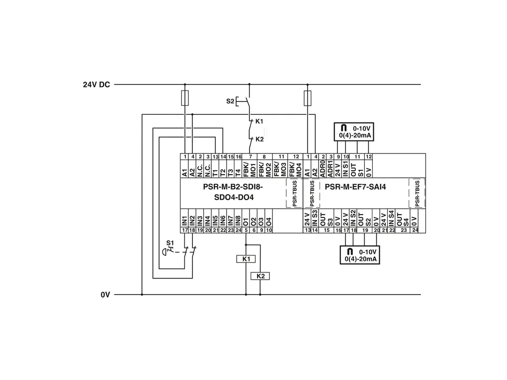
PSR-M-EF7-SAI4-SC - Extension module

Safe extension module with 4safe analog inputs, 0V...10V; 0mA or 4mA...20mA; TBUS interface, up to Cat.4/PLe, SIL3, plug-in screw terminal block, TBUS connector included
Cod. Articolo: 1104985 copia - copy
Cod. Fornitore: 1104985 copia - copy
PHOENIX CONTACT


Diminuisci la quantità
Aumenta la quantità
Caratteristiche Tecniche
Download
Caratteristiche Tecniche
Product propertiesProduct type: Safety device
Application: Analog IN
Insulation characteristics
Protection class: III
Times
Response time: see user manual
Restart time: min. 5 s (Boot time)
max. 10 s (Boot time)
Electrical propertiesMaximum power dissipation for nominal condition: 2.76 W (with max. permissible load)
Nominal operating mode: 100% operating factor
Interfaces: DIN rail TBUS for connection to the master module, supplied as standard
Air clearances and creepage distances
Rated insulation voltage: 250 VÂAC
Rated surge voltage/insulation: Basic insulation 4 kV between all current paths and housing
Electrical isolation, 0.5ÂkV functional insulation between logic and analog inputs and between the analog inputs
Supply
Designation: A1/A2
Rated control circuit supply voltage US: 19.2 VÂDC ... 28.8 VÂDC
24 VÂDC -20Â%Â/Â+20Â% (external fuse, typically 6ÂA)
Rated control supply current IS: typ. 82 mA (without sensor supply)
typ. 212 mA (with sensor supply)
Power consumption at US: typ. 1.96 W (without sensor supply)
typ. 5.08 W (with sensor supply)
Inrush current: max. 14 A (ΔtÂ=Â1Âms at Us)
Filter time: typ. 5 ms (in the event of voltage dips at Us)
Protective circuit: Serial protection against polarity reversal
Input dataGeneral
Protective circuit: Overload protection of the current inputs; Suppressor diode
Analog
Input name: INÂS1, INÂS2, INÂS3, INÂS4
Description of the input: Safety-oriented analog inputs, configurable as current or voltage inputs, galvanically isolated
Number of inputs: 4
Connection technology: 2-conductor, 3-conductor or 4-conductor (2-conductor sensor signal + 2-conductor sensor supply)
Note regarding the connection technology: shielded
Scanning rate: 2.5/5/10/16.6/20/50/60/100/200/400/800/1000/2000/4000ÂHz
Current input signal: 0 mA ... 25 mA (Measuring range)
0 mA ... 20 mA (Configurable measuring range with diagnostics range 20.1ÂmAÂ...Â23ÂmA)
4 mA ... 20 mA (Configurable measuring range with diagnostics range 20.1ÂmAÂ...Â23ÂmA (upper limit), 2.5ÂmAÂ...Â3.8ÂmA (lower limit))
Voltage input signal: 0 V ... 12 V (Measuring range)
0 V ... 10 V (Configurable measuring range with diagnostics range 10.05ÂVÂ...Â11.5ÂV (upper limit), 0.1ÂV (lower limit))
Max. permissible current: max. 35 mA (as current input)
Permissible voltage: max. 24 V (as current input)
max. 14 V (as voltage input)
Input resistance current input: 290 Ω ±25Â% (incl. internal protective circuit)
Input resistance of voltage input: 185 kΩ ±25Â%
A/D converter resolution: 16 bit
Resolution (current): 381 nA
Resolution (voltage): 152 µV
Precision: typ. ± 2 % (as current input, relative to the measuring range final value)
max. ± 2.5 % (as current input)
typ. ± 1 % (as voltage input, relative to the measuring range final value)
max. ± 1.5 % (as voltage input)
Temperature coefficients: typ. ± 0.07 %/K
max. ± 0.07 %/K
Limit frequency (3 dB): 160 Hz (RC low pass, 1stÂorder, as current input)
4 Hz (RC low pass, as voltage input)
Frequency: see user manual
Permissible cable length: max. 100 m (per input)
Protective circuit: Overload protection of the current inputs
Overload protection of the voltage inputs
Output dataSensor supply: OUTÂS1/0VÂ...OUTÂS4/0V
Description: Sensor supply voltage per analog input
Supply voltage: 24 VÂDC ±3Â%
Current: max. 30 mA (Sensor current recording per channel)
Short-circuit-proof: yes
Protective circuit: Overload protection Overload detection at Â38ÂmA
Connection dataConnection technology
pluggable: yes
Conductor connection
Connection method: Screw connection
Conductor cross section rigid: 0.2 mm² ... 2.5 mm²
Conductor cross section flexible: 0.2 mm² ... 2.5 mm²
Conductor cross-section AWG: 24 ... 12
Stripping length: 7 mm
Screw thread: M3
Tightening torque: 0.5 Nm ... 0.6 Nm
SignalingStatus display: 4x LED (yellow, red)
Operating voltage display: 1 x green LED
DimensionsWidth: 22.61 mm
Height: 112.58 mm
Depth: 113.6 mm
Material specificationsColor: yellow
Housing material: Polyamide PA non-reinforced
CharacteristicsSafety data
Stop category: 0
Safety data: ENÂISOÂ13849
Performance level (PL): e (2-channel wiring)
d (1-channel wiring)
Safety data: IEC 61508 - High-demand for 2-channel wiring
Safety Integrity Level (SIL): 3
Safety data: IEC 61508 - High-demand for 1-channel wiring
Safety Integrity Level (SIL): 2
Safety data: ENÂIEC 62061
Safety Integrity Level (SIL): 3 (2-channel wiring)
2 (1-channel wiring)
Environmental and real-life conditionsAmbient conditions
Degree of protection: IP20
Min. degree of protection of inst. location: IP54
Ambient temperature (operation): -10°C ... 55°C (observe derating)
Ambient temperature (storage/transport): -20°C ... 85°C
Maximum altitude: ≤ 2000 m (Above sea level)
Max. permissible humidity (storage/transport): 95 % (non-condensing)
Max. permissible relative humidity (operation): 95 % (non-condensing)
Shock: 10g for ΔtÂ=Â16Âms (continuous shock, 1000 shocks in each space direction)
Vibration (operation): 10ÂHzÂ...Â150ÂHz, 2g
ApprovalsCE
Identification: CE-compliant
MountingMounting type: DIN rail mounting
Assembly instructions: Observe derating
Mounting position: vertical or horizontal
Connection method: Screw connection
Download
PER SCARICARE I DOCUMENTI E' NECESSARIO EFFETTUARE L'ACCESSO AL SITO

Application_note_00183.pdf

Approvals_00901.pdf

Certification_00224.pdf

Certification_00318.pdf

Data_sheet_00645.pdf

Manual_00057.pdf

Manual_00058.pdf

Manufacturer_declaration_01348.pdf

Manufacturer_declaration_02189.pdf

Manufacturer_declaration_05475.pdf

Package_slip_01946.pdf

Technical_drawing_08536.pdf