Automazione Industriale

Meccatroinca

Meccatronica

Sicurezza Industriale

Componenti Quadri

Sensori e Sistemi di Visione

Pneumatica

Network e Comunicazione

Cavi Speciali

Accedi ai servizi

Entra nella tua area riservata

Accedi ai servizi

Entra nella tua area riservata

PHOENIX CONTACT 2905290
PHOENIX CONTACTNon disponibile

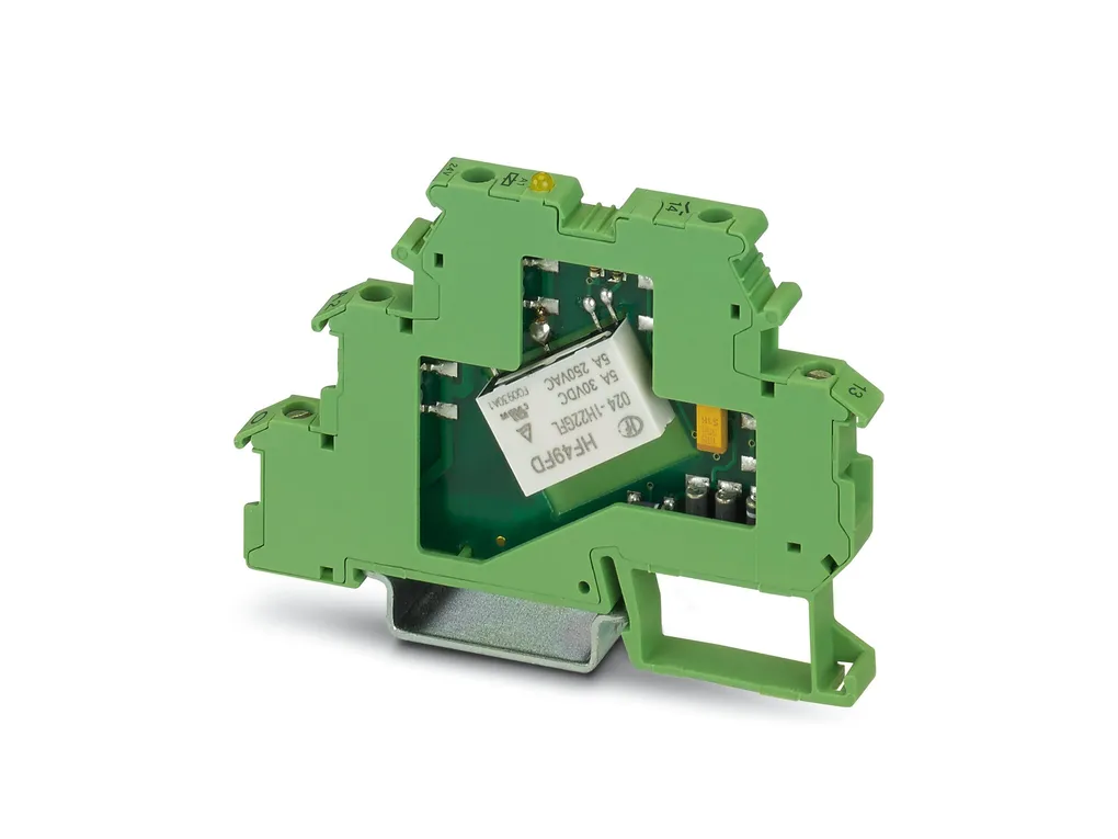
RIF-1-RPT-LV-230AC/1X21MS - Relay Module

Preassembled relay module with Push-in connection, consisting of: relay base, relay retaining bracket, plug-in interference suppression module, and power contact relay with test button and integrated status LED. Contact switching type: 1changeover contact. Input voltage: 230VAC
Cod. Articolo: 2905290 copia - copy
Cod. Fornitore: 2905290 copia - copy
PHOENIX CONTACT


Diminuisci la quantità
Aumenta la quantità
Caratteristiche Tecniche
Download
Caratteristiche Tecniche
Product propertiesProduct type: Relay Module
Product family: RIFLINEÂcomplete
Application: Universal
Palm switch
Operating mode: 100% operating factor
Mechanical service life: approx. 5x 10⁶ cycles
Insulation characteristics
Insulation: Safe isolation between input and output
Basic insulation between the changeover contacts
Insulation characteristicsâۉ€¹
Insulation: Safe isolation between input and output
Basic insulation between the changeover contacts
Overvoltage category: III
Pollution degree: 2
Electrical propertiesService life electrical: see diagram
Maximum power dissipation for nominal condition: 0.81 W
Test voltage (Winding/contact): 4 kVrms (50ÂHz, 1Âmin., winding/contact)
Rated insulation voltage: 250 VÂAC
Rated surge voltage: 6 kV (Input/output)
4 kV (between the changeover contacts)
Input dataCoil side
Nominal input voltage UN: 230 VÂAC (50/60ÂHz)
Input voltage range: 184 VÂAC ... 253 VÂAC (20°C)
Input voltage range in reference to UN: see diagram
Mains frequency: 50/60 Hz
Drive and function: monostable
Drive (polarity): polarized
Typical input current at UN: 3.5 mA
Typical response time: 4 ms ... 10 ms
Typical release time range: 3 ms ... 20 ms
Coil voltage: 230 VÂAC
Protective circuit: Varistor
Operating voltage display: Yellow LED
Output dataSwitching
Contact switching type: 1Âchangeover contact
Type of switch contact: Single contact
Contact material: AgNi
Maximum switching voltage: 250 V AC/DC
Minimum switching voltage: 12 V (10ÂmA)
Limiting continuous current: 8 A (see diagram)
Maximum inrush current: 32 A (20 ms, N/O contacts)
Min. switching current: 10 mA (12ÂV)
Interrupting rating (ohmic load) max.: 264 W (24ÂVÂDC)
62 W (48ÂVÂDC)
48 W (60ÂVÂDC)
52 W (110ÂVÂDC)
66 W (220ÂVÂDC)
2500 VA (250ÂVÂAC)
Switching capacity min.: 120 mW
Utilization category CB Scheme (IEC 60947-5-1): AC15, 3 A/250 V (N/O contact)
DC13, 2 A/24 V (N/O contact)
Connection dataConnection method: Push-in connection
Stripping length: 8 mm
Conductor cross section rigid: 0.14 mm² ... 1.5 mm²
Conductor cross section flexible: 0.14 mm² ... 1.5 mm²
0.14 mm² ... 1.5 mm² (Ferrule with plastic sleeve)
0.14 mm² ... 1 mm² (Ferrule with plastic sleeve, two conductors on double terminal block)
Conductor cross section AWG: 26 ... 16 (solid)
26 ... 16 (flexible)
DimensionsDrill hole
Diameter: 3.2 mm
Width: 16 mm
Height: 96 mm
Depth: 75 mm
Material specificationsFlammability rating according to UL 94: V2 (Housing)
Environmental and real-life conditionsAmbient conditions
Degree of protection (Relay base): IP20 (Relay base)
Degree of protection (Relay): RT II (Relay)
Ambient temperature (operation): -40°C ... 50°C
Ambient temperature (storage/transport): -40°C ... 85°C
ApprovalsCorrosive gas test
Identification: ISA-S71.04. G3 Harsh Group
ENÂ60068-2-60
Standards and regulationsStandards/regulations: IEC 60947-5-1
MountingMounting type: DIN rail mounting
Assembly instructions: in rows with zero spacing
Mounting position: any
Download
PER SCARICARE I DOCUMENTI E' NECESSARIO EFFETTUARE L'ACCESSO AL SITO

Application_note_00002.pdf

Application_note_00006.pdf

Approvals_01218.pdf

Manufacturer_declaration_16030.pdf

Package_slip_02192.pdf

Product_information_00033.pdf

Product_information_00745.pdf

Technical_drawing_40107.pdf